Product Description
Oririginal CHINAMFG Damper Actuator Servo Motor SQM41.261A21 For Industrial Combustion Heating
OVERVIEW
The SQM40…/SQM41… actuators are suited for driving oil pressure controller, butterfly valves, dampers or for use on other applications that require rotary motion. Areas of application are oil and gas burners of medium to higher capacity as well as thermal process plants. The actuators are used primarily for load-dependent control of the flow of gas, oil and combustion air:
– In connection with 3-position or modulating controllers (e.g. 4…20 mA), and/or …
– … directly by burner controls
PRODUCT PARAMETERS
| Name | Servo motor |
| Brand | Siemens |
| Model | SQM41.261A21 |
| Origin | Germany |
| Deliver Time | 3~15 days |
| Usage | gas burner accessories |
Analog inputs
General Linearity <5% of the control range Control range 0…90° or 0…135°, depending on type Voltage setpoint DC 2…10 V X1-1 (U-IN), X1-2 (GND)
– Umin DC 2 V
– Umax DC 10 V Input impedance ≥5 k Current setpoint DC 4…20 mA X1-3 (I-IN), X1-2 (GND)
– Imin DC 4 mA – Imax DC 20 mA Input impedance ≤500 Impedance setpoint 0…135 X1-4, X1-5, X1-6 (GND)
– RNominal 135 ±5%
RECOMMEND PRODUCTS
WARNING
1,Do not install it in the following places
(1)Places where special drugs or corrosive gases are present (e.g. ammonia, sulfur, hydrochloric acid, ethylene compounds, etc.)
(2)Places where water drops or is too wet.
(3) High temperature places.
(4) A place where the vibration lasts for a long time.
2, Please connect according to the specified basis.
3, In order to prevent electric shock and meter damage, please connect the power supply last. Misunderstanding that touching other subterminals can cause accidents and damage to the meter.
4,The load of each terminal connection should not exceed the rated value.
5,Please use the power supply with the same voltage and frequency as indicated by the machine.
6,For timers and auxiliary relays used as additional functions, please select reliable products and correctly form loops according to your needs.
7,Please ground according to the standard above D type grounding specified in the electrical equipment technical standard, and be sure to ground the burner body.
8,Do not tie the power cord and the high-voltage cable of the ignition transformer with the wire of the flame monitoring rod, and do not put it in the same wire tube, please wire separately.In particular, the high-voltage cable should be distributed separately, 10 cm away from the burner controller Above.
9,Please connect the ignition transformer high-voltage cable reliably to ensure that there is no bad contact. Poor contact will produce high frequency waves, radio noise, etc., causing misoperation. In addition, install the ignition transformer directly with the burner body or the metal part electrically connected to the burner body.
10,After connecting cables, ensure that the cables are correctly connected. Incorrect wiring may damage the unit or cause incorrect actions.
ABOUT US
company-HangZhou-YHG-Heating-Science-Technology-Co-ltd.html
/* January 22, 2571 19:08:37 */!function(){function s(e,r){var a,o={};try{e&&e.split(“,”).forEach(function(e,t){e&&(a=e.match(/(.*?):(.*)$/))&&1
| Certification: | CE, ISO |
|---|---|
| Customized: | Non-Customized |
| Surface Treatment: | Natural |
| Fuel: | Gas |
| Range of Applications: | Industrial |
| Type: | Servo Motor |
| Samples: |
US$ 400/Piece
1 Piece(Min.Order) | |
|---|
| Customization: |
Available
|
|
|---|
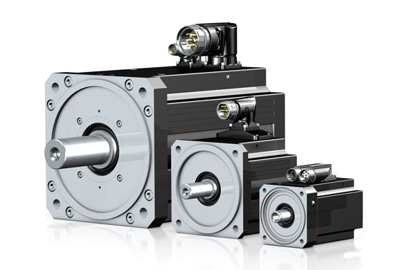
How are servo motors used in CNC machines and other precision machining equipment?
Servo motors play a crucial role in CNC (Computer Numerical Control) machines and other precision machining equipment. They provide precise and dynamic control over the movement of various axes, enabling high-accuracy positioning, rapid speed changes, and smooth motion profiles. Here’s a detailed explanation of how servo motors are used in CNC machines and precision machining equipment:
1. Axis Control:
CNC machines typically have multiple axes, such as X, Y, and Z for linear movements, as well as rotary axes for rotational movements. Servo motors are employed to drive each axis, converting electrical signals from the CNC controller into mechanical motion. The position, velocity, and acceleration of the servo motors are precisely controlled to achieve accurate and repeatable positioning of the machine’s tool or workpiece.
2. Feedback and Closed-Loop Control:
Servo motors in CNC machines are equipped with feedback devices, such as encoders or resolvers, to provide real-time information about the motor’s actual position. This feedback is used in a closed-loop control system, where the CNC controller continuously compares the desired position with the actual position and adjusts the motor’s control signals accordingly. This closed-loop control ensures accurate positioning and compensates for any errors, such as mechanical backlash or load variations.
3. Rapid and Precise Speed Changes:
Servo motors offer excellent dynamic response, allowing CNC machines to achieve rapid and precise speed changes during machining operations. By adjusting the control signals to the servo motors, the CNC controller can smoothly accelerate or decelerate the machine’s axes, resulting in efficient machining processes and reduced cycle times.
4. Contouring and Path Tracing:
CNC machines often perform complex machining tasks, such as contouring or following intricate paths. Servo motors enable precise path tracing by accurately controlling the position and velocity of the machine’s tool along the programmed path. This capability is crucial for producing intricate shapes, smooth curves, and intricate details with high precision.
5. Spindle Control:
In addition to axis control, servo motors are also used to control the spindle in CNC machines. The spindle motor, typically a servo motor, rotates the cutting tool or workpiece at the desired speed. Servo control ensures precise speed and torque control, allowing for optimal cutting conditions and surface finish quality.
6. Tool Changers and Automatic Tool Compensation:
CNC machines often feature automatic tool changers to switch between different cutting tools during machining operations. Servo motors are utilized to precisely position the tool changer mechanism, enabling quick and accurate tool changes. Additionally, servo motors can be used for automatic tool compensation, adjusting the tool’s position or orientation to compensate for wear, tool length variations, or tool offsets.
7. Synchronized Motion and Multi-Axis Coordination:
Servo motors enable synchronized motion and coordination between multiple axes in CNC machines. By precisely controlling the servo motors on different axes, complex machining operations involving simultaneous movements can be achieved. This capability is vital for tasks such as 3D contouring, thread cutting, and multi-axis machining.
In summary, servo motors are integral components of CNC machines and precision machining equipment. They provide accurate and dynamic control over the machine’s axes, enabling high-precision positioning, rapid speed changes, contouring, spindle control, tool changers, and multi-axis coordination. The combination of servo motor technology and CNC control systems allows for precise, efficient, and versatile machining operations in various industries.
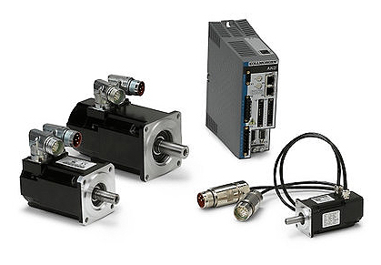
Are there different types of servo motors, and how do they differ?
Yes, there are different types of servo motors available, each with its own characteristics and applications. The variations among servo motors can be attributed to factors such as construction, control mechanisms, power requirements, and performance specifications. Let’s explore some of the common types of servo motors and how they differ:
1. DC Servo Motors:
DC servo motors are widely used in various applications. They consist of a DC motor combined with a feedback control system. The control system typically includes a position or velocity feedback sensor, such as an encoder or a resolver. DC servo motors offer good speed and torque control and are often employed in robotics, automation, and hobbyist projects. They can be operated with a separate motor driver or integrated into servo motor units with built-in control electronics.
2. AC Servo Motors:
AC servo motors are designed for high-performance applications that require precise control and fast response times. They are typically three-phase motors and are driven by sinusoidal AC waveforms. AC servo motors often incorporate advanced control algorithms and feedback systems to achieve accurate position, velocity, and torque control. These motors are commonly used in industrial automation, CNC machines, robotics, and other applications that demand high precision and dynamic performance.
3. Brushed Servo Motors:
Brushed servo motors feature a traditional brushed DC motor design. They consist of a rotor with a commutator and carbon brushes that make physical contact with the commutator. The brushes provide electrical connections, allowing the motor’s magnetic field to interact with the rotor’s windings. Brushed servo motors are known for their simplicity and cost-effectiveness. However, they may require more maintenance due to brush wear, and they generally have lower efficiency and shorter lifespan compared to brushless servo motors.
4. Brushless Servo Motors:
Brushless servo motors, also known as brushless DC (BLDC) motors, offer several advantages over brushed motors. They eliminate the need for brushes and commutators, resulting in improved reliability, higher efficiency, and longer lifespan. Brushless servo motors rely on electronic commutation, typically using Hall effect sensors or encoder feedback for accurate rotor position detection. These motors are widely used in robotics, industrial automation, aerospace, and other applications that require high-performance motion control with minimal maintenance.
5. Linear Servo Motors:
Linear servo motors are designed to provide linear motion instead of rotational motion. They consist of a primary part (stator) and a secondary part (slider or forcer) that interact magnetically to generate linear motion. Linear servo motors offer advantages such as high speed, high acceleration, and precise positioning along a linear axis. They find applications in various industries, including semiconductor manufacturing, packaging, printing, and machine tools.
6. Micro Servo Motors:
Micro servo motors are small-sized servo motors often used in applications with limited space and low power requirements. They are commonly found in hobbyist projects, model airplanes, remote-controlled vehicles, and small robotic systems. Micro servo motors are lightweight, compact, and offer reasonable precision and control for their size.
These are some of the different types of servo motors available, each catering to specific applications and requirements. The choice of servo motor type depends on factors such as the desired performance, accuracy, power requirements, environmental conditions, and cost considerations. Understanding the differences between servo motor types is essential for selecting the most suitable motor for a particular application.
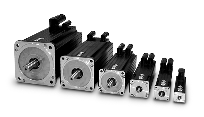
How does feedback control work in a servo motor system?
In a servo motor system, feedback control plays a crucial role in achieving precise control over the motor’s position, speed, and acceleration. The feedback control loop consists of several components that work together to continuously monitor and adjust the motor’s behavior based on the desired and actual position information. Here’s an overview of how feedback control works in a servo motor system:
1. Position Reference:
The servo motor system starts with a position reference or a desired position. This can be specified by a user or a control system, depending on the application requirements. The position reference represents the target position that the servo motor needs to reach and maintain.
2. Feedback Sensor:
A feedback sensor, such as an encoder or resolver, is attached to the servo motor’s shaft. The purpose of the feedback sensor is to continuously measure the motor’s actual position and provide feedback to the control system. The sensor generates signals that indicate the motor’s current position, allowing the control system to compare it with the desired position.
3. Control System:
The control system receives the position reference and the feedback signals from the sensor. It processes this information to determine the motor’s current position error, which is the difference between the desired position and the actual position. The control system calculates the required adjustments to minimize this position error and bring the motor closer to the desired position.
4. Controller:
The controller is a key component of the feedback control loop. It receives the position error from the control system and generates control signals that govern the motor’s behavior. The controller adjusts the motor’s inputs, such as voltage or current, based on the position error and control algorithm. The control algorithm can be implemented using various techniques, such as proportional-integral-derivative (PID) control, which adjusts the motor’s inputs based on the current error, the integral of past errors, and the rate of change of errors.
5. Motor Drive:
The control signals generated by the controller are sent to the motor drive unit, which amplifies and converts these signals into appropriate voltage or current levels. The motor drive unit provides the necessary power and control signals to the servo motor to initiate the desired motion. The drive unit adjusts the motor’s inputs based on the control signals to achieve the desired position, speed, and acceleration specified by the control system.
6. Motor Response:
As the motor receives the adjusted inputs from the motor drive, it starts to rotate and move towards the desired position. The motor’s response is continually monitored by the feedback sensor, which measures the actual position in real-time.
7. Feedback Comparison:
The feedback sensor compares the actual position with the desired position. If there is any deviation, the sensor generates feedback signals reflecting the discrepancy between the desired and actual positions. These signals are fed back to the control system, allowing it to recalculate the position error and generate updated control signals to further adjust the motor’s behavior.
This feedback loop continues to operate in a continuous cycle, with the control system adjusting the motor’s inputs based on the feedback information. As a result, the servo motor can accurately track and maintain the desired position, compensating for any disturbances or variations that may occur during operation.
In summary, feedback control in a servo motor system involves continuously comparing the desired position with the actual position using a feedback sensor. The control system processes this position error and generates control signals, which are converted and amplified by the motor drive unit to drive the motor. The motor’s response is monitored by the feedback sensor, and any discrepancies are fed back to the control system, enabling it to make further adjustments. This closed-loop control mechanism ensures precise positioning and accurate control of the servo motor.


editor by CX 2024-04-24
China Professional Factory Price Original CHINAMFG Sqn30.111A2700 Damper Actuator Servo Motor for Industrial Gas Burner vacuum pump oil
Product Description
Factory Price Original CHINAMFG SQN30.111A2700 Damper Actuator Servo Motor For Industrial Gas Burner
OVERVIEW
Spacious connection chamber for ease of installation
Actuators can be delivered ready installed on butterfly valves BVG, BVGF, BVA, BVAF, BVH, BVHS or linear flow control VFC
Actuator IC 40 is designed for all applications that require precise, controlled rotary movement between 0° and 90°. It can be mounted directly CHINAMFG the butterfy valves BVG, BVGF, BVA, BVAF, BVH, BVHS or linear fow control VFC in order to control the gas and air fow rates on gas burners. Actuators and butterfy valves or linear fow control VFC can also be delivered ready assembled as butterfy valves with actuatorIBG,IBGF,IBA,IBAF,IBH,IBHS orlinear fow control IFC.
PRODUCT PARAMETERS
| Name | Servo motor |
| Brand | Siemens |
| Model | SQN30.111A2700 |
| Origin | Germany |
| Deliver Time | 3~15 days |
| Usage | gas burner accessories |
TheIC 40 can be used on continuously-controlled burners and on stage-controlled burners.
Settings on the actuator IC 40 can be made using a PC with
the programming software BCSoft. All the relevant settings
for the process are made using the software via an optical
interface. Various operating modes, which may be modifed,
are stored in the unit. In addition, the control type (two-point
signal, three-point step signal or continuous control), running
times, adjustment angles and intermediate positions can be
programmed.
The actuator can also be controlled “by hand” using the soft-
ware.
Once set, all the parameters can be saved on the PC and
copied from there into other actuators, thus saving time dur-
ing the commissioning process.
Service technicians can call up statistical data using BCSoft,
such as hours of operation, actuating cycles and a fault history.
Some values can also be set to zero, for example to record
data over a specifc period of time.
Examples of application
For processes that require a homogeneous temperature dis-
tribution in the furnace. The actuator IC 40 is controlled by
a two-point controller and operates in On/Off or High/Low intermittent mode.
The actuator closes when the voltage sup-ply is interrupted. The running time can be adjusted between 5 and 25 seconds.
Function
The actuator IC 40 moves the butterfy valve towards 0° or 90°. There are 4 possible positions which the actuator can approach in steps. Any intermediate position is possible in continuous three-point step mode. Optionally, the actuator can also approach anyintermediate position via an additional current input.The slow fashing blue LED indicates that the motor of actuator IC 40is moving. The positionindicator on the housingindicates the opening angle. Further visualization and operation are performed on a PC using the BCSoft software.
RECOMMEND PRODUCTS
WARNING
1,Do not install it in the following places
(1)Places where special drugs or corrosive gases are present (e.g. ammonia, sulfur, hydrochloric acid, ethylene compounds, etc.)
(2)Places where water drops or is too wet.
(3) High temperature places.
(4) A place where the vibration lasts for a long time.
2, Please connect according to the specified basis.
3, In order to prevent electric shock and meter damage, please connect the power supply last. Misunderstanding that touching other subterminals can cause accidents and damage to the meter.
4,The load of each terminal connection should not exceed the rated value.
5,Please use the power supply with the same voltage and frequency as indicated by the machine.
6,For timers and auxiliary relays used as additional functions, please select reliable products and correctly form loops according to your needs.
7,Please ground according to the standard above D type grounding specified in the electrical equipment technical standard, and be sure to ground the burner body.
8,Do not tie the power cord and the high-voltage cable of the ignition transformer with the wire of the flame monitoring rod, and do not put it in the same wire tube, please wire separately.In particular, the high-voltage cable should be distributed separately, 10 cm away from the burner controller Above.
9,Please connect the ignition transformer high-voltage cable reliably to ensure that there is no bad contact. Poor contact will produce high frequency waves, radio noise, etc., causing misoperation. In addition, install the ignition transformer directly with the burner body or the metal part electrically connected to the burner body.
10,After connecting cables, ensure that the cables are correctly connected. Incorrect wiring may damage the unit or cause incorrect actions.
ABOUT US
company-HangZhou-YHG-Heating-Science-Technology-Co-ltd.html
/* January 22, 2571 19:08:37 */!function(){function s(e,r){var a,o={};try{e&&e.split(“,”).forEach(function(e,t){e&&(a=e.match(/(.*?):(.*)$/))&&1
| Certification: | CE, ISO |
|---|---|
| Customized: | Non-Customized |
| Surface Treatment: | Natural |
| Fuel: | Gas |
| Range of Applications: | Industrial |
| Type: | Servo Motor |
| Samples: |
US$ 250/Piece
1 Piece(Min.Order) | |
|---|
| Customization: |
Available
|
|
|---|

What maintenance practices are recommended for ensuring the longevity of servo motors?
Maintaining servo motors properly is crucial to ensure their longevity and reliable performance. Here are some recommended maintenance practices:
1. Regular Cleaning:
Regularly clean the servo motor to remove dust, debris, and other contaminants that can affect its performance. Use a soft brush or compressed air to clean the motor’s exterior and ventilation ports. Avoid using excessive force or liquid cleaners that could damage the motor.
2. Lubrication:
Follow the manufacturer’s recommendations for lubrication intervals and use the appropriate lubricant for the motor. Lubricate the motor’s bearings, gears, and other moving parts as per the specified schedule. Proper lubrication reduces friction, minimizes wear, and helps maintain optimal performance.
3. Inspections:
Regularly inspect the servo motor for signs of wear, damage, or loose connections. Check for any unusual noises, vibrations, or overheating during operation, as these can indicate potential issues. If any abnormalities are detected, consult the manufacturer’s documentation or seek professional assistance for further evaluation and repair.
4. Electrical Connections:
Ensure that all electrical connections to the servo motor, such as power cables and signal wires, are secure and properly insulated. Loose or damaged connections can lead to electrical problems, voltage fluctuations, or signal interference, which can affect the motor’s performance and longevity.
5. Environmental Considerations:
Take into account the operating environment of the servo motor. Ensure that the motor is protected from excessive moisture, dust, extreme temperatures, and corrosive substances. If necessary, use appropriate enclosures or protective measures to safeguard the motor from adverse environmental conditions.
6. Software and Firmware Updates:
Stay updated with the latest software and firmware releases provided by the servo motor manufacturer. These updates often include bug fixes, performance enhancements, and new features that can improve the motor’s functionality and reliability. Follow the manufacturer’s instructions for safely updating the motor’s software or firmware.
7. Training and Documentation:
Ensure that personnel responsible for the maintenance of servo motors are properly trained and familiar with the manufacturer’s guidelines and documentation. This includes understanding recommended maintenance procedures, safety precautions, and troubleshooting techniques. Regular training and access to up-to-date documentation are essential for effective servo motor maintenance.
8. Professional Servicing:
If a servo motor requires complex repairs or servicing beyond regular maintenance, it is advisable to consult a qualified technician or contact the manufacturer’s service center. Attempting to repair or modify the motor without proper expertise can lead to further damage or safety hazards.
By following these maintenance practices, servo motors can operate optimally and have an extended lifespan. Regular cleaning, lubrication, inspections, secure electrical connections, environmental considerations, software updates, training, and professional servicing all contribute to ensuring the longevity and reliable performance of servo motors.
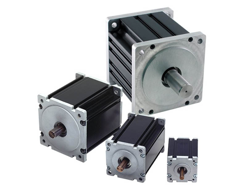
How is the size of a servo motor determined based on application requirements?
The size of a servo motor is an important consideration when selecting a motor for a specific application. The size of the motor is determined based on various factors related to the application requirements. Let’s explore how the size of a servo motor is determined:
1. Torque Requirements:
One of the primary factors in determining the size of a servo motor is the torque requirements of the application. The motor should be able to generate sufficient torque to handle the load and overcome any resistance or friction in the system. The required torque depends on factors such as the weight of the load, the distance from the motor’s axis of rotation, and any additional forces acting on the system. By analyzing the torque requirements, one can select a servo motor with an appropriate size and torque rating to meet the application’s needs.
2. Speed and Acceleration Requirements:
The desired speed and acceleration capabilities of the application also influence the size of the servo motor. Different applications have varying speed and acceleration requirements, and the motor needs to be capable of achieving the desired performance. Higher speeds and accelerations may require larger motors with more powerful components to handle the increased forces and stresses. By considering the required speed and acceleration, one can determine the size of the motor that can meet these demands.
3. Inertia and Load Inertia Ratio:
The inertia of the load and the inertia ratio between the load and the servo motor are important considerations in sizing the motor. Inertia refers to the resistance of an object to changes in its rotational motion. If the load has a high inertia, it requires a servo motor with sufficient size and torque to accelerate and decelerate the load effectively. The inertia ratio, which is the ratio of the load inertia to the motor inertia, affects the motor’s ability to control the load’s motion accurately. A proper balance between the load and motor inertia is necessary to achieve optimal performance and stability in the system.
4. Duty Cycle and Continuous Operation:
The duty cycle and continuous operation requirements of the application also impact the motor size selection. Duty cycle refers to the ratio of the motor’s operating time to the total cycle time. Applications with high-duty cycles or continuous operation may require larger motors that can handle sustained operation without overheating or performance degradation. It is important to consider the motor’s continuous torque rating and thermal characteristics to ensure it can operate reliably under the given duty cycle requirements.
5. Physical Space Constraints:
The physical space available for installing the servo motor is another factor to consider. The motor’s dimensions should fit within the available space, considering factors such as motor length, diameter, and any mounting requirements. It is essential to ensure that the chosen motor can be easily integrated into the system without interfering with other components or causing space constraints.
6. Weight Limitations:
The weight limitations of the application may influence the motor size selection. If there are weight restrictions, such as in mobile or lightweight applications, it is necessary to choose a servo motor that is compact and lightweight while still providing the required performance. Lighter servo motors can help optimize the overall weight and balance of the system.
7. Cost Considerations:
Cost is also a factor to consider when determining the size of a servo motor. Larger motors with higher torque and performance capabilities tend to be more expensive. It is important to strike a balance between the required performance and the cost constraints of the application. Analyzing the cost-effectiveness and overall value of the motor in relation to the application requirements is essential.
By considering these factors, one can determine the appropriate size of a servo motor that can meet the specific application requirements. It is advisable to consult with manufacturers or experts in the field to ensure the chosen motor size aligns with the application needs and provides optimal performance and reliability.
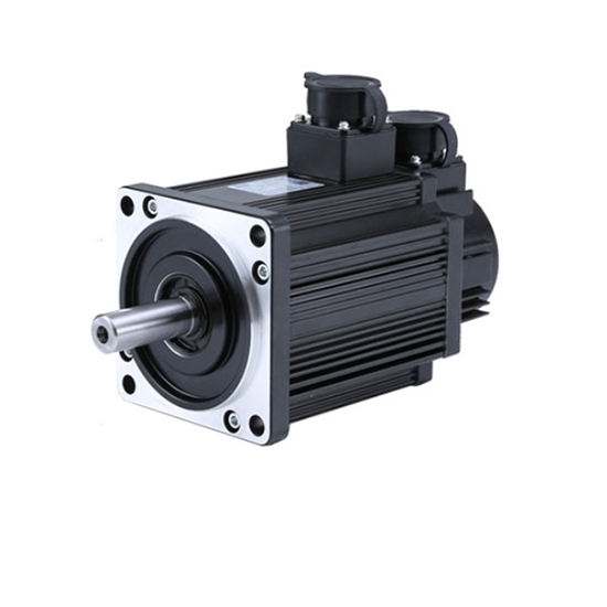
What is a servo motor, and how does it function in automation systems?
A servo motor is a type of motor specifically designed for precise control of angular or linear position, velocity, and acceleration. It is widely used in various automation systems where accurate motion control is required. Let’s explore the concept of servo motors and how they function in automation systems:
A servo motor consists of a motor, a position feedback device (such as an encoder or resolver), and a control system. The control system receives input signals, typically in the form of electrical pulses or analog signals, indicating the desired position or speed. Based on these signals and the feedback from the position sensor, the control system adjusts the motor’s operation to achieve the desired motion.
The functioning of a servo motor in an automation system involves the following steps:
- Signal Input: The automation system provides a control signal to the servo motor, indicating the desired position, speed, or other motion parameters. This signal can be generated by a human operator, a computer, a programmable logic controller (PLC), or other control devices.
- Feedback System: The servo motor incorporates a position feedback device, such as an encoder or resolver, which continuously monitors the motor’s actual position. This feedback information is sent back to the control system, allowing it to compare the actual position with the desired position specified by the input signal.
- Control System: The control system, typically housed within the servo motor or an external servo drive, receives the input signal and the feedback from the position sensor. It processes this information and generates the appropriate control signals to the motor.
- Motor Operation: Based on the control signals received from the control system, the servo motor adjusts its operation to achieve the desired motion. The control system varies the motor’s voltage, current, or frequency to control the motor’s speed, torque, or position accurately.
- Closed-Loop Control: Servo motors operate in a closed-loop control system. The feedback information from the position sensor allows the control system to continuously monitor and adjust the motor’s operation to minimize any deviation between the desired position and the actual position. This closed-loop control mechanism provides high accuracy, repeatability, and responsiveness in motion control applications.
One of the key advantages of servo motors in automation systems is their ability to provide precise and dynamic motion control. They can rapidly accelerate, decelerate, and change direction with high accuracy, allowing for intricate and complex movements. Servo motors are widely used in applications such as robotics, CNC machines, printing presses, packaging equipment, and automated manufacturing systems.
In summary, a servo motor is a specialized motor that enables accurate control of position, velocity, and acceleration in automation systems. Through the combination of a control system and a position feedback device, servo motors can precisely adjust their operation to achieve the desired motion. Their closed-loop control mechanism and high responsiveness make them an essential component in various applications requiring precise and dynamic motion control.


editor by CX 2024-04-19
China Good quality Azbil New or Ecm3000f0350 Flow Control Valve Servo Damper Actuator Motor for Burners Accessories vacuum pump oil
Product Description
AZBIL New OR ECM3000F 0571 Flow Control Valve Servo Damper Actuator Motor For Burners Accessories
Product Description
The ECM3000 is a control motor designed for various industrial equipment applications. Two models are available: 90° angular stroke motor for applications such as burner controls and 160° angular stroke motor for valve controls of hot and cold water or steam. Three kinds of control signal input types are available: relay contact, 4 to 20mAdc, and potentiometer. Three kinds of power supply voltage types are available: 24Vac, 100Vac and 200Vac. Additionally, a power supply unit applicable to a voltag erange of 85 to 264Vac is also available for the 4 to 20mAdc input type. The ECM3000 contains a standard bracket accessory for
retrofitting Yamatake’s older motors.
Features:
• Robust aluminum die-cast body.
• Long life parts are used for the internal potentiometers and bearings of the motor.
• Input is selectable – 3 input types. (According to model No.) Relay contact, 4 to 20mAdc and potentiometer.
• The 90° angular stroke motor type has a pointer to indicate the position of the rotating shaft and a rotating direction label.
• Four optional auxiliary switches are available with the 90° angular stroke motor type. Control Motor ECM3000
• For both 90° and 160° angular stroke motors, models with 2 auxiliary switches and open/close override function are alsoavailable.
• Splash-proof structure
IP54 or equivalent, superior to environment resistance.
• Motor mounting bracket (standard accessory part) is compatible to replacing from Yamatake’s older motor being used at present.
• Two angular strokes available for several applications. 90° type
and 160° type
• Output torque is 12.5N·m.
• A CE-marked and cUL-certified product (24Vac model only).
PRODUCT SPECIFICATIONS
|
item |
value |
|
Condition |
New |
|
Warranty |
1.5 years |
|
Applicable Industries |
Machinery Repair Shops, Food & Beverage Factory, Farms, Home Use, Retail, Food Shop, Construction works , Food & Beverage Shops, Other, Advertising Company |
|
Weight (KG) |
2 |
|
Video outgoing-inspection |
Provided |
|
Machinery Test Report |
Provided |
|
Place of CHINAMFG |
Japan |
|
Brand Name |
AZBIL |
|
Type |
Gas Burner |
|
Product name |
AZBIL ECM3000F 0571 Flow Control Valve Damper Actuator |
|
Model |
ECM3000F 0571 |
|
Brand |
AZBIL |
|
Color |
Silver |
|
Power supply |
24vac |
|
Turnaround Time |
39s |
|
Input Signal |
Relay contact |
|
Output torque |
12.5Nm |
|
Application/Usage |
Gas Burners Industrial Accessories |
|
After Warranty Service |
Video technical support |
AZBIL New OR ECM3000F 0571 Flow Control Valve Servo Damper Actuator Motor For Burners Accessories
Recommend Products
/* January 22, 2571 19:08:37 */!function(){function s(e,r){var a,o={};try{e&&e.split(“,”).forEach(function(e,t){e&&(a=e.match(/(.*?):(.*)$/))&&1
| Usage: | Hydrogen, Nitrogen, Ng and LPG |
|---|---|
| Purpose: | Control Gas |
| Parts: | Damper Actuator |
| Application Fields: | Industrial Gas Burner |
| Noise Level: | Low |
| Machine Size: | Medium |
| Samples: |
US$ 985/Piece
1 Piece(Min.Order) | |
|---|
| Customization: |
Available
|
|
|---|
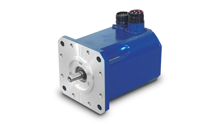
How does the cost of servo motors vary based on their specifications and features?
The cost of servo motors can vary significantly based on their specifications and features. Several factors influence the price of servo motors, and understanding these factors can help in selecting the most cost-effective option for a specific application. Let’s explore in detail how the cost of servo motors can vary:
1. Power Rating:
One of the primary factors affecting the cost of a servo motor is its power rating, which is typically measured in watts or kilowatts. Higher power-rated servo motors generally cost more than lower-rated ones due to the increased materials and manufacturing required to handle higher power levels. The power rating of a servo motor is determined by the torque and speed requirements of the application. Higher torque and speed capabilities often correspond to higher costs.
2. Torque and Speed:
The torque and speed capabilities of a servo motor directly impact its cost. Servo motors designed for high torque and high-speed applications tend to be more expensive due to the need for robust construction, specialized materials, and advanced control electronics. Motors with higher torque and speed ratings often require more powerful magnets, larger windings, and higher precision components, contributing to the increase in cost.
3. Frame Size:
The physical size or frame size of a servo motor also plays a role in determining its cost. Servo motors come in various frame sizes, such as NEMA (National Electrical Manufacturers Association) standard sizes in North America. Larger frame sizes generally command higher prices due to the increased materials and manufacturing complexity required to build larger motors. Smaller frame sizes, on the other hand, may be more cost-effective but may have limitations in terms of torque and speed capabilities.
4. Feedback Mechanism:
The feedback mechanism used in a servo motor affects its cost. Servo motors typically employ encoders or resolvers to provide feedback on the rotor position. Higher-resolution encoders or more advanced feedback technologies can increase the cost of the motor. For example, servo motors with absolute encoders, which provide position information even after power loss, tend to be more expensive than those with incremental encoders.
5. Control Features and Technology:
The control features and technology incorporated into a servo motor can influence its cost. Advanced servo motors may offer features such as built-in controllers, fieldbus communication interfaces, advanced motion control algorithms, or integrated safety functions. These additional features contribute to the cost of the motor but can provide added value and convenience in certain applications. Standard servo motors with basic control functionality may be more cost-effective for simpler applications.
6. Brand and Reputation:
The brand and reputation of the servo motor manufacturer can impact its cost. Established and reputable brands often command higher prices due to factors such as quality assurance, reliability, technical support, and extensive product warranties. While motors from less-known or generic brands may be more affordable, they may not offer the same level of performance, reliability, or long-term support.
7. Customization and Application-Specific Requirements:
If a servo motor needs to meet specific customization or application-specific requirements, such as specialized mounting options, environmental sealing, or compliance with industry standards, the cost may increase. Customization often involves additional engineering, design, and manufacturing efforts, which can lead to higher prices compared to off-the-shelf servo motors.
It’s important to note that the cost of a servo motor is not the sole indicator of its quality or suitability for a particular application. It is essential to carefully evaluate the motor’s specifications, features, and performance characteristics in relation to the application requirements to make an informed decision.
In summary, the cost of servo motors varies based on factors such as power rating, torque and speed capabilities, frame size, feedback mechanism, control features and technology, brand reputation, and customization requirements. By considering these factors and comparing different options, it is possible to select a servo motor that strikes the right balance between performance and cost-effectiveness for a specific application.

Are there different types of servo motors, and how do they differ?
Yes, there are different types of servo motors available, each with its own characteristics and applications. The variations among servo motors can be attributed to factors such as construction, control mechanisms, power requirements, and performance specifications. Let’s explore some of the common types of servo motors and how they differ:
1. DC Servo Motors:
DC servo motors are widely used in various applications. They consist of a DC motor combined with a feedback control system. The control system typically includes a position or velocity feedback sensor, such as an encoder or a resolver. DC servo motors offer good speed and torque control and are often employed in robotics, automation, and hobbyist projects. They can be operated with a separate motor driver or integrated into servo motor units with built-in control electronics.
2. AC Servo Motors:
AC servo motors are designed for high-performance applications that require precise control and fast response times. They are typically three-phase motors and are driven by sinusoidal AC waveforms. AC servo motors often incorporate advanced control algorithms and feedback systems to achieve accurate position, velocity, and torque control. These motors are commonly used in industrial automation, CNC machines, robotics, and other applications that demand high precision and dynamic performance.
3. Brushed Servo Motors:
Brushed servo motors feature a traditional brushed DC motor design. They consist of a rotor with a commutator and carbon brushes that make physical contact with the commutator. The brushes provide electrical connections, allowing the motor’s magnetic field to interact with the rotor’s windings. Brushed servo motors are known for their simplicity and cost-effectiveness. However, they may require more maintenance due to brush wear, and they generally have lower efficiency and shorter lifespan compared to brushless servo motors.
4. Brushless Servo Motors:
Brushless servo motors, also known as brushless DC (BLDC) motors, offer several advantages over brushed motors. They eliminate the need for brushes and commutators, resulting in improved reliability, higher efficiency, and longer lifespan. Brushless servo motors rely on electronic commutation, typically using Hall effect sensors or encoder feedback for accurate rotor position detection. These motors are widely used in robotics, industrial automation, aerospace, and other applications that require high-performance motion control with minimal maintenance.
5. Linear Servo Motors:
Linear servo motors are designed to provide linear motion instead of rotational motion. They consist of a primary part (stator) and a secondary part (slider or forcer) that interact magnetically to generate linear motion. Linear servo motors offer advantages such as high speed, high acceleration, and precise positioning along a linear axis. They find applications in various industries, including semiconductor manufacturing, packaging, printing, and machine tools.
6. Micro Servo Motors:
Micro servo motors are small-sized servo motors often used in applications with limited space and low power requirements. They are commonly found in hobbyist projects, model airplanes, remote-controlled vehicles, and small robotic systems. Micro servo motors are lightweight, compact, and offer reasonable precision and control for their size.
These are some of the different types of servo motors available, each catering to specific applications and requirements. The choice of servo motor type depends on factors such as the desired performance, accuracy, power requirements, environmental conditions, and cost considerations. Understanding the differences between servo motor types is essential for selecting the most suitable motor for a particular application.
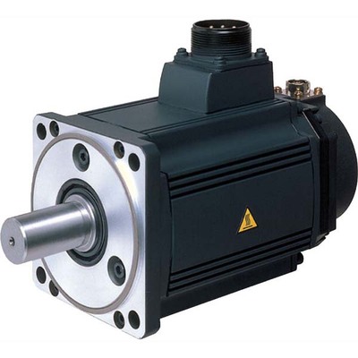
Can you explain the difference between a servo motor and a regular electric motor?
A servo motor and a regular electric motor are both types of electric motors, but they have distinct differences in terms of design, control, and functionality.
A regular electric motor, also known as an induction motor or a DC motor, is designed to convert electrical energy into mechanical energy. It consists of a rotor, which rotates, and a stator, which surrounds the rotor and generates a rotating magnetic field. The rotor is connected to an output shaft, and when current flows through the motor’s windings, it creates a magnetic field that interacts with the stator’s magnetic field, resulting in rotational motion.
On the other hand, a servo motor is a more specialized type of electric motor that incorporates additional components for precise control of position, speed, and acceleration. It consists of a regular electric motor, a sensor or encoder, and a feedback control system. The sensor or encoder provides feedback on the motor’s current position, and this information is used by the control system to adjust the motor’s behavior.
The key difference between a servo motor and a regular electric motor lies in their control mechanisms. A regular electric motor typically operates at a fixed speed based on the voltage and frequency of the power supply. In contrast, a servo motor can be controlled to rotate to a specific angle or position and maintain that position accurately. The control system continuously monitors the motor’s actual position through the feedback sensor and adjusts the motor’s operation to achieve the desired position or follow a specific trajectory.
Another distinction is the torque output of the motors. Regular electric motors generally provide high torque at low speeds and lower torque at higher speeds. In contrast, servo motors are designed to deliver high torque at both low and high speeds, which makes them suitable for applications that require precise and dynamic motion control.
Furthermore, servo motors often have a more compact and lightweight design compared to regular electric motors. They are commonly used in applications where precise positioning, speed control, and responsiveness are critical, such as robotics, CNC machines, automation systems, and remote-controlled vehicles.
In summary, while both servo motors and regular electric motors are used to convert electrical energy into mechanical energy, servo motors offer enhanced control capabilities, precise positioning, and high torque at various speeds, making them well-suited for applications that require accurate and dynamic motion control.


editor by CX 2024-04-04