Product Description
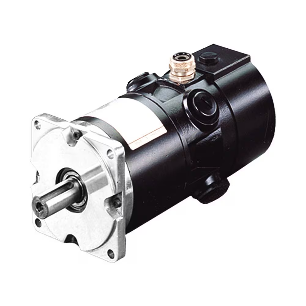
| Brushless Servo Motor Series 110ST-M | ||||||||
| Specification | Unit | 110ST-M2030 | 110ST-M4571 | 110ST-M4030 | 110ST-M5030 | 110ST-M6571 | 110ST-M6030 | |
| Rated voltage | U | V | 220VAC -15%-+10% 50/60Hz (300VDC) | |||||
| Rated output power | P out | W | 600 | 800 | 1200 | 1500 | 1200 | 1600 |
| Rated speed | n N | rpm | 3000 | 2000 | 3000 | 3000 | 2000 | 3000 |
| Rated current | I N | A | 2.5 | 3.5 | 5 | 6 | 5 | 6.6 |
| Rated torque | T N | N.m | 2 | 4 | 4 | 5 | 6 | 6 |
| Peak current | I P | A | 7.5 | 10.5 | 15 | 18 | 15 | 19.9 |
| Peak torque | T p | N.m | 6 | 12 | 12 | 15 | 18 | 18 |
| Rotor inertia | J | Kg.cm 2 | 3.2 | 6.5 | 6.5 | 8.2 | 9.9 | 9.9 |
| Encoder | CPR | 2500 | 2500 | 2500 | 2500 | 2500 | 2500 | |
| IP Code | IP65 | IP65 | IP65 | IP65 | IP65 | IP65 | ||
| Winding class | Class F Continuous | |||||||
| Motor weight | 4 | 5 | 5 | 5.7 | 6 | 6 | ||
| Remark | Motor are available with different winding and mechanical modification to meet specific applications. | |||||||
| Lead-wires’ Spec To Encoder | |||||||||||||||
| Color | BLU | BLU | GRN | GRN | YLW | YLW | BRN | BRN | GRY | GRY | WHT | WHT | RED | BLK | Shield |
| /BLK | /BLK | /BLK | /BLK | /BLK | /BLK | ||||||||||
| Description | A+ | A- | B+ | B- | Z+ | Z- | U+ | U- | V+ | V- | W+ | W- | Vcc | GND | Shield |
| Plug Pin# | 1 | 2 | 3 | 4 | 5 | 6 | 7 | 8 | 9 | 10 | 11 | 12 | 13 | 14 | 15 |
| To Motor | ||||
| Color | RED | YLW | BLU | YLW/GRN |
| Description | U | V | W | GND |
| Plug Pin# | 1 | 2 | 3 | 4 |
FAQ
Q: How to order?
A: send us inquiry → receive our quotation → negotiate details → confirm the sample → sign contract/deposit → mass production → cargo ready → balance/delivery → further cooperation.
Q: How about Sample order?
A: Sample is available for you. please contact us for details.
Q: Which shipping way is avaliable?
A: DHL, UPS, FedEx, TNT, EMS, China Post,Sea are available.The other shipping ways are also available, please contact us if you need ship by the other shipping way.
Q: How long is the deliver?
A: Devliver time depends on the quantity you order. usually it takes 15-25 working days.
Q: My package has missing products. What can I do?
A: Please contact our support team and we will confirm your order with the package contents.We apologize for any inconveniences.
Q: How to confirm the payment?
A: We accept payment by T/T, PayPal, the other payment ways also could be accepted,Please contact us before you pay by the other payment ways. Also 30-50% deposit is available, the balance money should be paid before shipping. /* March 10, 2571 17:59:20 */!function(){function s(e,r){var a,o={};try{e&&e.split(“,”).forEach(function(e,t){e&&(a=e.match(/(.*?):(.*)$/))&&1
| Application: | Industrial |
|---|---|
| Speed: | High Speed |
| Function: | Driving |
| Casing Protection: | Closed Type |
| Certification: | ISO9001, CCC, SGS |
| Brand: | Sunrise Motor |
| Samples: |
US$ 115/Piece
1 Piece(Min.Order) | |
|---|
| Customization: |
Available
|
|
|---|

Are there advancements or trends in servo motor technology that users should be aware of?
Yes, there have been significant advancements and emerging trends in servo motor technology that users should be aware of. These developments aim to enhance performance, improve efficiency, and provide new capabilities. Here are some noteworthy advancements and trends in servo motor technology:
1. Higher Power Density:
Advancements in servo motor design and manufacturing techniques have led to higher power densities. This means that modern servo motors can deliver more power in a smaller and lighter package. Higher power density allows for more compact and efficient machine designs, particularly in applications with limited space or weight restrictions.
2. Improved Efficiency:
Efficiency is a crucial aspect of servo motor technology. Manufacturers are continuously striving to improve motor efficiency to minimize energy consumption and reduce operating costs. Advanced motor designs, optimized winding configurations, and the use of high-quality materials contribute to higher efficiency levels, resulting in energy savings and lower heat generation.
3. Integration of Electronics and Control:
Integration of electronics and control functions directly into servo motors is becoming increasingly common. This trend eliminates the need for external motor controllers or drives, simplifies wiring and installation, and reduces overall system complexity. Integrated servo motors often include features such as on-board motion control, communication interfaces, and safety features.
4. Digitalization and Connectivity:
Servo motor technology is embracing digitalization and connectivity trends. Many modern servo motors come equipped with digital interfaces, such as Ethernet or fieldbus protocols, enabling seamless integration with industrial communication networks. This connectivity allows for real-time monitoring, diagnostics, and remote control of servo motors, facilitating condition monitoring, predictive maintenance, and system optimization.
5. Advanced Feedback Systems:
Feedback systems play a critical role in servo motor performance. Recent advancements in feedback technology have resulted in more accurate and higher-resolution encoders, resolvers, and sensors. These advanced feedback systems provide precise position and velocity information, enabling improved motion control, better accuracy, and enhanced dynamic response in servo motor applications.
6. Smart and Adaptive Control Algorithms:
Servo motor control algorithms have evolved to include smart and adaptive features. These algorithms can adapt to changing load conditions, compensate for disturbances, and optimize motor performance based on real-time feedback. Smart control algorithms contribute to smoother operation, increased stability, and improved tracking accuracy in various applications.
7. Safety and Functional Safety:
Safety is a paramount concern in industrial automation. Servo motor technology has incorporated safety features and functional safety standards to ensure the protection of personnel and equipment. Safety-rated servo motors often include features such as safe torque off (STO) functionality, safe motion control, and compliance with safety standards like ISO 13849 and IEC 61508.
It’s important for users to stay informed about these advancements and trends in servo motor technology. By understanding the latest developments, users can make informed decisions when selecting and implementing servo motors, leading to improved performance, efficiency, and reliability in their applications.

How is the size of a servo motor determined based on application requirements?
The size of a servo motor is an important consideration when selecting a motor for a specific application. The size of the motor is determined based on various factors related to the application requirements. Let’s explore how the size of a servo motor is determined:
1. Torque Requirements:
One of the primary factors in determining the size of a servo motor is the torque requirements of the application. The motor should be able to generate sufficient torque to handle the load and overcome any resistance or friction in the system. The required torque depends on factors such as the weight of the load, the distance from the motor’s axis of rotation, and any additional forces acting on the system. By analyzing the torque requirements, one can select a servo motor with an appropriate size and torque rating to meet the application’s needs.
2. Speed and Acceleration Requirements:
The desired speed and acceleration capabilities of the application also influence the size of the servo motor. Different applications have varying speed and acceleration requirements, and the motor needs to be capable of achieving the desired performance. Higher speeds and accelerations may require larger motors with more powerful components to handle the increased forces and stresses. By considering the required speed and acceleration, one can determine the size of the motor that can meet these demands.
3. Inertia and Load Inertia Ratio:
The inertia of the load and the inertia ratio between the load and the servo motor are important considerations in sizing the motor. Inertia refers to the resistance of an object to changes in its rotational motion. If the load has a high inertia, it requires a servo motor with sufficient size and torque to accelerate and decelerate the load effectively. The inertia ratio, which is the ratio of the load inertia to the motor inertia, affects the motor’s ability to control the load’s motion accurately. A proper balance between the load and motor inertia is necessary to achieve optimal performance and stability in the system.
4. Duty Cycle and Continuous Operation:
The duty cycle and continuous operation requirements of the application also impact the motor size selection. Duty cycle refers to the ratio of the motor’s operating time to the total cycle time. Applications with high-duty cycles or continuous operation may require larger motors that can handle sustained operation without overheating or performance degradation. It is important to consider the motor’s continuous torque rating and thermal characteristics to ensure it can operate reliably under the given duty cycle requirements.
5. Physical Space Constraints:
The physical space available for installing the servo motor is another factor to consider. The motor’s dimensions should fit within the available space, considering factors such as motor length, diameter, and any mounting requirements. It is essential to ensure that the chosen motor can be easily integrated into the system without interfering with other components or causing space constraints.
6. Weight Limitations:
The weight limitations of the application may influence the motor size selection. If there are weight restrictions, such as in mobile or lightweight applications, it is necessary to choose a servo motor that is compact and lightweight while still providing the required performance. Lighter servo motors can help optimize the overall weight and balance of the system.
7. Cost Considerations:
Cost is also a factor to consider when determining the size of a servo motor. Larger motors with higher torque and performance capabilities tend to be more expensive. It is important to strike a balance between the required performance and the cost constraints of the application. Analyzing the cost-effectiveness and overall value of the motor in relation to the application requirements is essential.
By considering these factors, one can determine the appropriate size of a servo motor that can meet the specific application requirements. It is advisable to consult with manufacturers or experts in the field to ensure the chosen motor size aligns with the application needs and provides optimal performance and reliability.

How does feedback control work in a servo motor system?
In a servo motor system, feedback control plays a crucial role in achieving precise control over the motor’s position, speed, and acceleration. The feedback control loop consists of several components that work together to continuously monitor and adjust the motor’s behavior based on the desired and actual position information. Here’s an overview of how feedback control works in a servo motor system:
1. Position Reference:
The servo motor system starts with a position reference or a desired position. This can be specified by a user or a control system, depending on the application requirements. The position reference represents the target position that the servo motor needs to reach and maintain.
2. Feedback Sensor:
A feedback sensor, such as an encoder or resolver, is attached to the servo motor’s shaft. The purpose of the feedback sensor is to continuously measure the motor’s actual position and provide feedback to the control system. The sensor generates signals that indicate the motor’s current position, allowing the control system to compare it with the desired position.
3. Control System:
The control system receives the position reference and the feedback signals from the sensor. It processes this information to determine the motor’s current position error, which is the difference between the desired position and the actual position. The control system calculates the required adjustments to minimize this position error and bring the motor closer to the desired position.
4. Controller:
The controller is a key component of the feedback control loop. It receives the position error from the control system and generates control signals that govern the motor’s behavior. The controller adjusts the motor’s inputs, such as voltage or current, based on the position error and control algorithm. The control algorithm can be implemented using various techniques, such as proportional-integral-derivative (PID) control, which adjusts the motor’s inputs based on the current error, the integral of past errors, and the rate of change of errors.
5. Motor Drive:
The control signals generated by the controller are sent to the motor drive unit, which amplifies and converts these signals into appropriate voltage or current levels. The motor drive unit provides the necessary power and control signals to the servo motor to initiate the desired motion. The drive unit adjusts the motor’s inputs based on the control signals to achieve the desired position, speed, and acceleration specified by the control system.
6. Motor Response:
As the motor receives the adjusted inputs from the motor drive, it starts to rotate and move towards the desired position. The motor’s response is continually monitored by the feedback sensor, which measures the actual position in real-time.
7. Feedback Comparison:
The feedback sensor compares the actual position with the desired position. If there is any deviation, the sensor generates feedback signals reflecting the discrepancy between the desired and actual positions. These signals are fed back to the control system, allowing it to recalculate the position error and generate updated control signals to further adjust the motor’s behavior.
This feedback loop continues to operate in a continuous cycle, with the control system adjusting the motor’s inputs based on the feedback information. As a result, the servo motor can accurately track and maintain the desired position, compensating for any disturbances or variations that may occur during operation.
In summary, feedback control in a servo motor system involves continuously comparing the desired position with the actual position using a feedback sensor. The control system processes this position error and generates control signals, which are converted and amplified by the motor drive unit to drive the motor. The motor’s response is monitored by the feedback sensor, and any discrepancies are fed back to the control system, enabling it to make further adjustments. This closed-loop control mechanism ensures precise positioning and accurate control of the servo motor.


editor by CX 2024-02-14