Product Description
Product Description:
1.Flexspline is a hollow flanging standard cylinder structure.
2.There is a large-diameter hollow shaft hole in the middle of the cam of the wave generator. The internal design of the reducer has a support bearing.
3.It has a fully sealed structure and is easy to install. It is very suitable for the occasions where the wire needs to be threaded from the center of the reducer.
Advantages:
The first:High precision,high torque
The second:dedicated technical personnel can be on-the-go to provide design solutions
The third:Factory direct sales fine workmanship durable quality assurance
The fourth:Product quality issues have a one-year warranty time, can be returned for replacement or repair
Company profile:
HangZhou CHINAMFG Technology Co., Ltd. established in 2014, is committed to the R & D plant of high-precision transmission components. At present, the annual production capacity can reach 45000 sets of harmonic reducers. We firmly believe in quality first. All links from raw materials to finished products are strictly supervised and controlled, which provides a CHINAMFG foundation for product quality. Our products are sold all over the country and abroad.
The harmonic reducer and other high-precision transmission components were independently developed by the company. Our company spends 20% of its sales every year on the research and development of new technologies in the industry. There are 5 people in R & D.
Our advantage is as below:
1.7 years of marketing experience
2. 5-person R & D team to provide you with technical support
3. It is sold at home and abroad and exported to Turkey and Ireland
4. The product quality is guaranteed with a one-year warranty
5. Products can be customized
Strength factory:
Our plant has an entire campus The number of workshops is around 300 Whether it’s from the production of raw materials and the procurement of raw materials to the inspection of finished products, we’re doing it ourselves. There is a complete production system
HST-III Parameter:
| Model | Speed ratio | Enter the rated torque at 2000r/min | Allowed CHINAMFG torque at start stop | The allowable maximum of the average load torque | Maximum torque is allowed in an instant | Allow the maximum speed to be entered | Average input speed is allowed | Back gap | design life | ||||
| NM | kgfm | NM | kgfm | NM | kgfm | NM | kgfm | r / min | r / min | Arc sec | Hour | ||
| 14 | 50 | 6.2 | 0.6 | 20.7 | 2.1 | 7.9 | 0.7 | 40.3 | 4.1 | 7000 | 3000 | ≤30 | 10000 |
| 80 | 9 | 0.9 | 27 | 2.7 | 12.7 | 1.3 | 54.1 | 5.5 | |||||
| 100 | 9 | 0.9 | 32 | 3.3 | 12.7 | 1.3 | 62.1 | 6.3 | |||||
| 17 | 50 | 18.4 | 1.9 | 39 | 4 | 29.9 | 3 | 80.5 | 8.2 | 6500 | 3000 | ≤30 | 15000 |
| 80 | 25.3 | 2.6 | 49.5 | 5 | 31 | 3.2 | 100.1 | 10.2 | |||||
| 100 | 27.6 | 2.8 | 62 | 6.3 | 45 | 4.6 | 124.2 | 12.7 | |||||
| 20 | 50 | 28.8 | 2.9 | 64.4 | 6.6 | 39 | 4 | 112.7 | 11.5 | 5600 | 3000 | ≤30 | 15000 |
| 80 | 39.1 | 4 | 85 | 8.8 | 54 | 5.5 | 146.1 | 14.9 | |||||
| 100 | 46 | 4.7 | 94.3 | 9.6 | 56 | 5.8 | 169.1 | 17.2 | |||||
| 120 | 46 | 4.7 | 100 | 10.2 | 56 | 5.8 | 169.1 | 17.2 | |||||
| 160 | 46 | 4.7 | 100 | 10.2 | 56 | 5.8 | 169.1 | 17.2 | |||||
| 25 | 50 | 44.9 | 4.6 | 113 | 11.5 | 63 | 6.5 | 213.9 | 21.8 | 4800 | 3000 | ≤30 | 15000 |
| 80 | 72.5 | 7.4 | 158 | 16.1 | 100 | 10.2 | 293.3 | 29.9 | |||||
| 100 | 77.1 | 7.9 | 181 | 18.4 | 124 | 12.7 | 326.6 | 33.3 | |||||
| 120 | 77.1 | 7.9 | 192 | 19.6 | 124 | 12.7 | 349.6 | 35.6 | |||||
| 32 | 50 | 87.4 | 8.9 | 248 | 25.3 | 124 | 12.7 | 439 | 44.8 | 4000 | 3000 | ≤30 | 15000 |
| 80 | 135.7 | 13.8 | 350 | 35.6 | 192 | 19.6 | 653 | 66.6 | |||||
| 100 | 157.6 | 16.1 | 383 | 39.1 | 248 | 25.3 | 744 | 75.9 | |||||
| 40 | 100 | 308 | 37.2 | 660 | 67 | 432 | 44 | 1232 | 126.7 | 4000 | 3000 | ≤30 | 15000 |
HSG Parameter:
| Model | Speed ratio | Enter the rated torque at 2000r/min | Allowed CHINAMFG torque at start stop | The allowable maximum of the average load torque | Maximum torque is allowed in an instant | Allow the maximum speed to be entered | Average input speed is allowed | Back gap | design life | ||||
| NM | kgfm | NM | kgfm | NM | kgfm | NM | kgfm | r / min | r / min | Arc sec | Hour | ||
| 14 | 50 | 7 | 0.7 | 23 | 2.3 | 9 | 0.9 | 46 | 4.7 | 14000 | 8500 | ≤20 | 15000 |
| 80 | 10 | 1 | 30 | 3.1 | 14 | 1.4 | 61 | 6.2 | |||||
| 100 | 10 | 1 | 36 | 3.7 | 14 | 1.4 | 70 | 7.2 | |||||
| 17 | 50 | 21 | 2.1 | 44 | 4.5 | 34 | 3.4 | 91 | 9 | 10000 | 7300 | ≤20 | 20000 |
| 80 | 29 | 2.9 | 56 | 5.7 | 35 | 3.6 | 113 | 12 | |||||
| 100 | 31 | 3.2 | 70 | 7.2 | 51 | 5.2 | 143 | 15 | |||||
| 20 | 50 | 33 | 3.3 | 73 | 7.4 | 44 | 4.5 | 127 | 13 | 10000 | 6500 | ≤20 | 20000 |
| 80 | 44 | 4.5 | 96 | 9.8 | 61 | 6.2 | 165 | 17 | |||||
| 100 | 52 | 5.3 | 107 | 10.9 | 64 | 6.5 | 191 | 20 | |||||
| 120 | 52 | 5.3 | 113 | 11.5 | 64 | 6.5 | 191 | 20 | |||||
| 160 | 52 | 5.3 | 120 | 12.2 | 64 | 6.5 | 191 | 20 | |||||
| 25 | 50 | 51 | 5.2 | 127 | 13 | 72 | 7.3 | 242 | 25 | 7500 | 5600 | ≤20 | 20000 |
| 80 | 82 | 8.4 | 178 | 18 | 113 | 12 | 332 | 34 | |||||
| 100 | 87 | 8.9 | 204 | 21 | 140 | 14 | 369 | 38 | |||||
| 120 | 87 | 8.9 | 217 | 22 | 140 | 14 | 395 | 40 | |||||
| 32 | 50 | 99 | 10 | 281 | 29 | 140 | 14 | 497 | 51 | 7000 | 4800 | ≤20 | 20000 |
| 80 | 153 | 16 | 395 | 40 | 217 | 22 | 738 | 75 | |||||
| 100 | 178 | 18 | 433 | 44 | 281 | 29 | 841 | 86 | |||||
| 40 | 100 | 345 | 35 | 738 | 75 | 484 | 49 | 1400 | 143 | 5600 | 4000 | ≤20 | 20000 |
Exhibition:
Application case:
FQA:
Q: What should I provide when I choose gearbox/speed reducer?
A: The best way is to provide the motor drawing with parameter. Our engineer will check and recommend the most suitable gearbox model for your refer.
Or you can also provide below specification as well:
1) Type, model and torque.
2) Ratio or output speed
3) Working condition and connection method
4) Quality and installed machine name
5) Input mode and input speed
6) Motor brand model or flange and motor shaft size
/* January 22, 2571 19:08:37 */!function(){function s(e,r){var a,o={};try{e&&e.split(“,”).forEach(function(e,t){e&&(a=e.match(/(.*?):(.*)$/))&&1
| Application: | Motor, Electric Cars, Motorcycle, Machinery, Marine, Car |
|---|---|
| Hardness: | Hardened Tooth Surface |
| Installation: | 90 Degree |
| Layout: | Coaxial |
| Gear Shape: | Cylindrical Gear |
| Step: | Single-Step |
| Customization: |
Available
|
|
|---|

Are there advancements or trends in servo motor technology that users should be aware of?
Yes, there have been significant advancements and emerging trends in servo motor technology that users should be aware of. These developments aim to enhance performance, improve efficiency, and provide new capabilities. Here are some noteworthy advancements and trends in servo motor technology:
1. Higher Power Density:
Advancements in servo motor design and manufacturing techniques have led to higher power densities. This means that modern servo motors can deliver more power in a smaller and lighter package. Higher power density allows for more compact and efficient machine designs, particularly in applications with limited space or weight restrictions.
2. Improved Efficiency:
Efficiency is a crucial aspect of servo motor technology. Manufacturers are continuously striving to improve motor efficiency to minimize energy consumption and reduce operating costs. Advanced motor designs, optimized winding configurations, and the use of high-quality materials contribute to higher efficiency levels, resulting in energy savings and lower heat generation.
3. Integration of Electronics and Control:
Integration of electronics and control functions directly into servo motors is becoming increasingly common. This trend eliminates the need for external motor controllers or drives, simplifies wiring and installation, and reduces overall system complexity. Integrated servo motors often include features such as on-board motion control, communication interfaces, and safety features.
4. Digitalization and Connectivity:
Servo motor technology is embracing digitalization and connectivity trends. Many modern servo motors come equipped with digital interfaces, such as Ethernet or fieldbus protocols, enabling seamless integration with industrial communication networks. This connectivity allows for real-time monitoring, diagnostics, and remote control of servo motors, facilitating condition monitoring, predictive maintenance, and system optimization.
5. Advanced Feedback Systems:
Feedback systems play a critical role in servo motor performance. Recent advancements in feedback technology have resulted in more accurate and higher-resolution encoders, resolvers, and sensors. These advanced feedback systems provide precise position and velocity information, enabling improved motion control, better accuracy, and enhanced dynamic response in servo motor applications.
6. Smart and Adaptive Control Algorithms:
Servo motor control algorithms have evolved to include smart and adaptive features. These algorithms can adapt to changing load conditions, compensate for disturbances, and optimize motor performance based on real-time feedback. Smart control algorithms contribute to smoother operation, increased stability, and improved tracking accuracy in various applications.
7. Safety and Functional Safety:
Safety is a paramount concern in industrial automation. Servo motor technology has incorporated safety features and functional safety standards to ensure the protection of personnel and equipment. Safety-rated servo motors often include features such as safe torque off (STO) functionality, safe motion control, and compliance with safety standards like ISO 13849 and IEC 61508.
It’s important for users to stay informed about these advancements and trends in servo motor technology. By understanding the latest developments, users can make informed decisions when selecting and implementing servo motors, leading to improved performance, efficiency, and reliability in their applications.

Can you explain the concept of torque and speed in relation to servo motors?
Torque and speed are two essential parameters in understanding the performance characteristics of servo motors. Let’s explore these concepts in relation to servo motors:
Torque:
Torque refers to the rotational force produced by a servo motor. It determines the motor’s ability to generate rotational motion and overcome resistance or load. Torque is typically measured in units of force multiplied by distance, such as Nm (Newton-meter) or oz-in (ounce-inch).
The torque output of a servo motor is crucial in applications where the motor needs to move or control a load. The motor must provide enough torque to overcome the resistance or friction in the system and maintain the desired position or motion. Higher torque allows the motor to handle heavier loads or more challenging operating conditions.
It is important to note that the torque characteristics of a servo motor may vary depending on the speed or position of the motor. Manufacturers often provide torque-speed curves or torque-position curves, which illustrate the motor’s torque capabilities at different operating points. Understanding these curves helps in selecting a servo motor that can deliver the required torque for a specific application.
Speed:
Speed refers to the rotational velocity at which a servo motor operates. It indicates how fast the motor can rotate and how quickly it can achieve the desired position or motion. Speed is typically measured in units of revolutions per minute (RPM) or radians per second (rad/s).
The speed of a servo motor is crucial in applications that require rapid movements or high-speed operations. It determines the motor’s responsiveness and the system’s overall performance. Different servo motors have different speed capabilities, and the maximum achievable speed is often specified by the manufacturer.
It is worth noting that the speed of a servo motor may also affect its torque output. Some servo motors exhibit a phenomenon known as “speed-torque curve,” where the motor’s torque decreases as the speed increases. This behavior is influenced by factors such as motor design, winding resistance, and control algorithms. Understanding the speed-torque characteristics of a servo motor is important for selecting a motor that can meet the speed requirements of the application while maintaining sufficient torque.
Overall, torque and speed are interrelated parameters that determine the performance capabilities of a servo motor. The torque capability determines the motor’s ability to handle loads, while the speed capability determines how quickly the motor can achieve the desired motion. When selecting a servo motor, it is essential to consider both the torque and speed requirements of the application to ensure that the motor can deliver the desired performance.

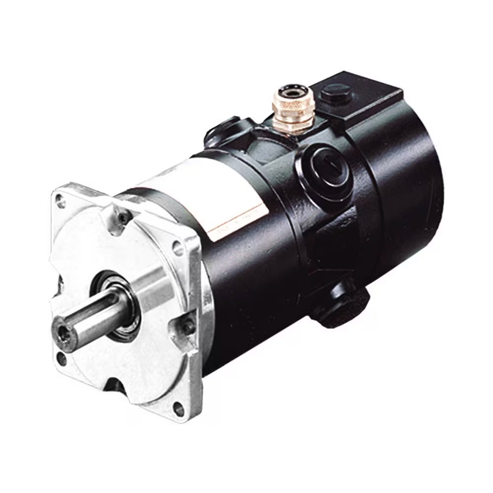
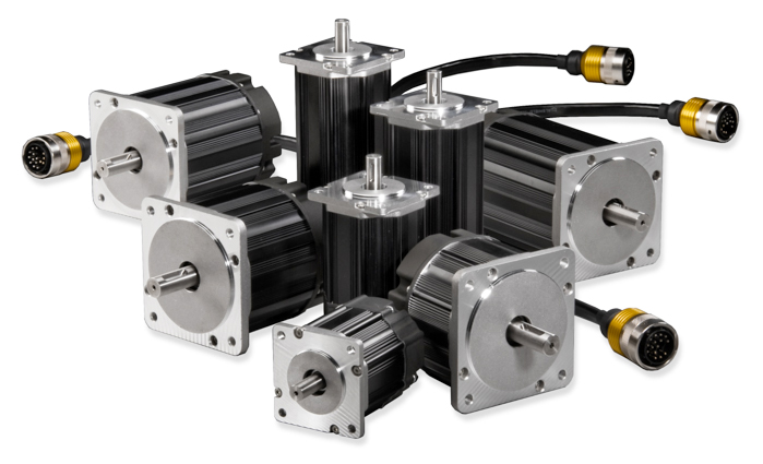
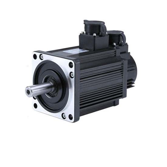
What is a servo motor, and how does it function in automation systems?
A servo motor is a type of motor specifically designed for precise control of angular or linear position, velocity, and acceleration. It is widely used in various automation systems where accurate motion control is required. Let’s explore the concept of servo motors and how they function in automation systems:
A servo motor consists of a motor, a position feedback device (such as an encoder or resolver), and a control system. The control system receives input signals, typically in the form of electrical pulses or analog signals, indicating the desired position or speed. Based on these signals and the feedback from the position sensor, the control system adjusts the motor’s operation to achieve the desired motion.
The functioning of a servo motor in an automation system involves the following steps:
- Signal Input: The automation system provides a control signal to the servo motor, indicating the desired position, speed, or other motion parameters. This signal can be generated by a human operator, a computer, a programmable logic controller (PLC), or other control devices.
- Feedback System: The servo motor incorporates a position feedback device, such as an encoder or resolver, which continuously monitors the motor’s actual position. This feedback information is sent back to the control system, allowing it to compare the actual position with the desired position specified by the input signal.
- Control System: The control system, typically housed within the servo motor or an external servo drive, receives the input signal and the feedback from the position sensor. It processes this information and generates the appropriate control signals to the motor.
- Motor Operation: Based on the control signals received from the control system, the servo motor adjusts its operation to achieve the desired motion. The control system varies the motor’s voltage, current, or frequency to control the motor’s speed, torque, or position accurately.
- Closed-Loop Control: Servo motors operate in a closed-loop control system. The feedback information from the position sensor allows the control system to continuously monitor and adjust the motor’s operation to minimize any deviation between the desired position and the actual position. This closed-loop control mechanism provides high accuracy, repeatability, and responsiveness in motion control applications.
One of the key advantages of servo motors in automation systems is their ability to provide precise and dynamic motion control. They can rapidly accelerate, decelerate, and change direction with high accuracy, allowing for intricate and complex movements. Servo motors are widely used in applications such as robotics, CNC machines, printing presses, packaging equipment, and automated manufacturing systems.
In summary, a servo motor is a specialized motor that enables accurate control of position, velocity, and acceleration in automation systems. Through the combination of a control system and a position feedback device, servo motors can precisely adjust their operation to achieve the desired motion. Their closed-loop control mechanism and high responsiveness make them an essential component in various applications requiring precise and dynamic motion control.


editor by CX 2024-05-09