Product Description
Product Description:
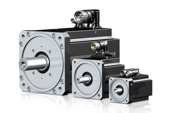
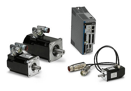
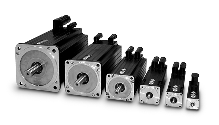
H series permanent magnet synchronous motor is a high efficiency and energy saving motor independently developed and produced by Hui Xunjun. It uses permanent magnet material to generate magnetic field, which has high efficiency, reliable operation, small size, light weight, energy saving and environmental protection, and low noise. It can be matched with servo drive, and realize precise walking and reversing through cooperative motion between servo drive and servo drive, realizing fast response, high stability and high precision control in the whole motion control process. According to the customer’s own characteristics can quickly provide professional customized services. Widely used in machine tools, textile, rewinding, air compressor, fan pump and other industries.
Name plate:
180 series specifications:
Product Feature:
Technical Specification:
Scope of application:
DIMENSION:(UNIT:MM)
Factory outline:
/* January 22, 2571 19:08:37 */!function(){function s(e,r){var a,o={};try{e&&e.split(“,”).forEach(function(e,t){e&&(a=e.match(/(.*?):(.*)$/))&&1
| Application: | Industrial |
|---|---|
| Function: | Driving |
| Casing Protection: | Protection Type |
| Number of Poles: | 4 |
| Starting Mode: | Direct on-line Starting |
| Certification: | ISO9001 |
| Customization: |
Available
|
|
|---|

How are servo motors used in CNC machines and other precision machining equipment?
Servo motors play a crucial role in CNC (Computer Numerical Control) machines and other precision machining equipment. They provide precise and dynamic control over the movement of various axes, enabling high-accuracy positioning, rapid speed changes, and smooth motion profiles. Here’s a detailed explanation of how servo motors are used in CNC machines and precision machining equipment:
1. Axis Control:
CNC machines typically have multiple axes, such as X, Y, and Z for linear movements, as well as rotary axes for rotational movements. Servo motors are employed to drive each axis, converting electrical signals from the CNC controller into mechanical motion. The position, velocity, and acceleration of the servo motors are precisely controlled to achieve accurate and repeatable positioning of the machine’s tool or workpiece.
2. Feedback and Closed-Loop Control:
Servo motors in CNC machines are equipped with feedback devices, such as encoders or resolvers, to provide real-time information about the motor’s actual position. This feedback is used in a closed-loop control system, where the CNC controller continuously compares the desired position with the actual position and adjusts the motor’s control signals accordingly. This closed-loop control ensures accurate positioning and compensates for any errors, such as mechanical backlash or load variations.
3. Rapid and Precise Speed Changes:
Servo motors offer excellent dynamic response, allowing CNC machines to achieve rapid and precise speed changes during machining operations. By adjusting the control signals to the servo motors, the CNC controller can smoothly accelerate or decelerate the machine’s axes, resulting in efficient machining processes and reduced cycle times.
4. Contouring and Path Tracing:
CNC machines often perform complex machining tasks, such as contouring or following intricate paths. Servo motors enable precise path tracing by accurately controlling the position and velocity of the machine’s tool along the programmed path. This capability is crucial for producing intricate shapes, smooth curves, and intricate details with high precision.
5. Spindle Control:
In addition to axis control, servo motors are also used to control the spindle in CNC machines. The spindle motor, typically a servo motor, rotates the cutting tool or workpiece at the desired speed. Servo control ensures precise speed and torque control, allowing for optimal cutting conditions and surface finish quality.
6. Tool Changers and Automatic Tool Compensation:
CNC machines often feature automatic tool changers to switch between different cutting tools during machining operations. Servo motors are utilized to precisely position the tool changer mechanism, enabling quick and accurate tool changes. Additionally, servo motors can be used for automatic tool compensation, adjusting the tool’s position or orientation to compensate for wear, tool length variations, or tool offsets.
7. Synchronized Motion and Multi-Axis Coordination:
Servo motors enable synchronized motion and coordination between multiple axes in CNC machines. By precisely controlling the servo motors on different axes, complex machining operations involving simultaneous movements can be achieved. This capability is vital for tasks such as 3D contouring, thread cutting, and multi-axis machining.
In summary, servo motors are integral components of CNC machines and precision machining equipment. They provide accurate and dynamic control over the machine’s axes, enabling high-precision positioning, rapid speed changes, contouring, spindle control, tool changers, and multi-axis coordination. The combination of servo motor technology and CNC control systems allows for precise, efficient, and versatile machining operations in various industries.

Are there different types of servo motors, and how do they differ?
Yes, there are different types of servo motors available, each with its own characteristics and applications. The variations among servo motors can be attributed to factors such as construction, control mechanisms, power requirements, and performance specifications. Let’s explore some of the common types of servo motors and how they differ:
1. DC Servo Motors:
DC servo motors are widely used in various applications. They consist of a DC motor combined with a feedback control system. The control system typically includes a position or velocity feedback sensor, such as an encoder or a resolver. DC servo motors offer good speed and torque control and are often employed in robotics, automation, and hobbyist projects. They can be operated with a separate motor driver or integrated into servo motor units with built-in control electronics.
2. AC Servo Motors:
AC servo motors are designed for high-performance applications that require precise control and fast response times. They are typically three-phase motors and are driven by sinusoidal AC waveforms. AC servo motors often incorporate advanced control algorithms and feedback systems to achieve accurate position, velocity, and torque control. These motors are commonly used in industrial automation, CNC machines, robotics, and other applications that demand high precision and dynamic performance.
3. Brushed Servo Motors:
Brushed servo motors feature a traditional brushed DC motor design. They consist of a rotor with a commutator and carbon brushes that make physical contact with the commutator. The brushes provide electrical connections, allowing the motor’s magnetic field to interact with the rotor’s windings. Brushed servo motors are known for their simplicity and cost-effectiveness. However, they may require more maintenance due to brush wear, and they generally have lower efficiency and shorter lifespan compared to brushless servo motors.
4. Brushless Servo Motors:
Brushless servo motors, also known as brushless DC (BLDC) motors, offer several advantages over brushed motors. They eliminate the need for brushes and commutators, resulting in improved reliability, higher efficiency, and longer lifespan. Brushless servo motors rely on electronic commutation, typically using Hall effect sensors or encoder feedback for accurate rotor position detection. These motors are widely used in robotics, industrial automation, aerospace, and other applications that require high-performance motion control with minimal maintenance.
5. Linear Servo Motors:
Linear servo motors are designed to provide linear motion instead of rotational motion. They consist of a primary part (stator) and a secondary part (slider or forcer) that interact magnetically to generate linear motion. Linear servo motors offer advantages such as high speed, high acceleration, and precise positioning along a linear axis. They find applications in various industries, including semiconductor manufacturing, packaging, printing, and machine tools.
6. Micro Servo Motors:
Micro servo motors are small-sized servo motors often used in applications with limited space and low power requirements. They are commonly found in hobbyist projects, model airplanes, remote-controlled vehicles, and small robotic systems. Micro servo motors are lightweight, compact, and offer reasonable precision and control for their size.
These are some of the different types of servo motors available, each catering to specific applications and requirements. The choice of servo motor type depends on factors such as the desired performance, accuracy, power requirements, environmental conditions, and cost considerations. Understanding the differences between servo motor types is essential for selecting the most suitable motor for a particular application.

How does feedback control work in a servo motor system?
In a servo motor system, feedback control plays a crucial role in achieving precise control over the motor’s position, speed, and acceleration. The feedback control loop consists of several components that work together to continuously monitor and adjust the motor’s behavior based on the desired and actual position information. Here’s an overview of how feedback control works in a servo motor system:
1. Position Reference:
The servo motor system starts with a position reference or a desired position. This can be specified by a user or a control system, depending on the application requirements. The position reference represents the target position that the servo motor needs to reach and maintain.
2. Feedback Sensor:
A feedback sensor, such as an encoder or resolver, is attached to the servo motor’s shaft. The purpose of the feedback sensor is to continuously measure the motor’s actual position and provide feedback to the control system. The sensor generates signals that indicate the motor’s current position, allowing the control system to compare it with the desired position.
3. Control System:
The control system receives the position reference and the feedback signals from the sensor. It processes this information to determine the motor’s current position error, which is the difference between the desired position and the actual position. The control system calculates the required adjustments to minimize this position error and bring the motor closer to the desired position.
4. Controller:
The controller is a key component of the feedback control loop. It receives the position error from the control system and generates control signals that govern the motor’s behavior. The controller adjusts the motor’s inputs, such as voltage or current, based on the position error and control algorithm. The control algorithm can be implemented using various techniques, such as proportional-integral-derivative (PID) control, which adjusts the motor’s inputs based on the current error, the integral of past errors, and the rate of change of errors.
5. Motor Drive:
The control signals generated by the controller are sent to the motor drive unit, which amplifies and converts these signals into appropriate voltage or current levels. The motor drive unit provides the necessary power and control signals to the servo motor to initiate the desired motion. The drive unit adjusts the motor’s inputs based on the control signals to achieve the desired position, speed, and acceleration specified by the control system.
6. Motor Response:
As the motor receives the adjusted inputs from the motor drive, it starts to rotate and move towards the desired position. The motor’s response is continually monitored by the feedback sensor, which measures the actual position in real-time.
7. Feedback Comparison:
The feedback sensor compares the actual position with the desired position. If there is any deviation, the sensor generates feedback signals reflecting the discrepancy between the desired and actual positions. These signals are fed back to the control system, allowing it to recalculate the position error and generate updated control signals to further adjust the motor’s behavior.
This feedback loop continues to operate in a continuous cycle, with the control system adjusting the motor’s inputs based on the feedback information. As a result, the servo motor can accurately track and maintain the desired position, compensating for any disturbances or variations that may occur during operation.
In summary, feedback control in a servo motor system involves continuously comparing the desired position with the actual position using a feedback sensor. The control system processes this position error and generates control signals, which are converted and amplified by the motor drive unit to drive the motor. The motor’s response is monitored by the feedback sensor, and any discrepancies are fed back to the control system, enabling it to make further adjustments. This closed-loop control mechanism ensures precise positioning and accurate control of the servo motor.


editor by CX 2024-03-07