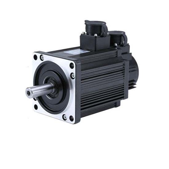
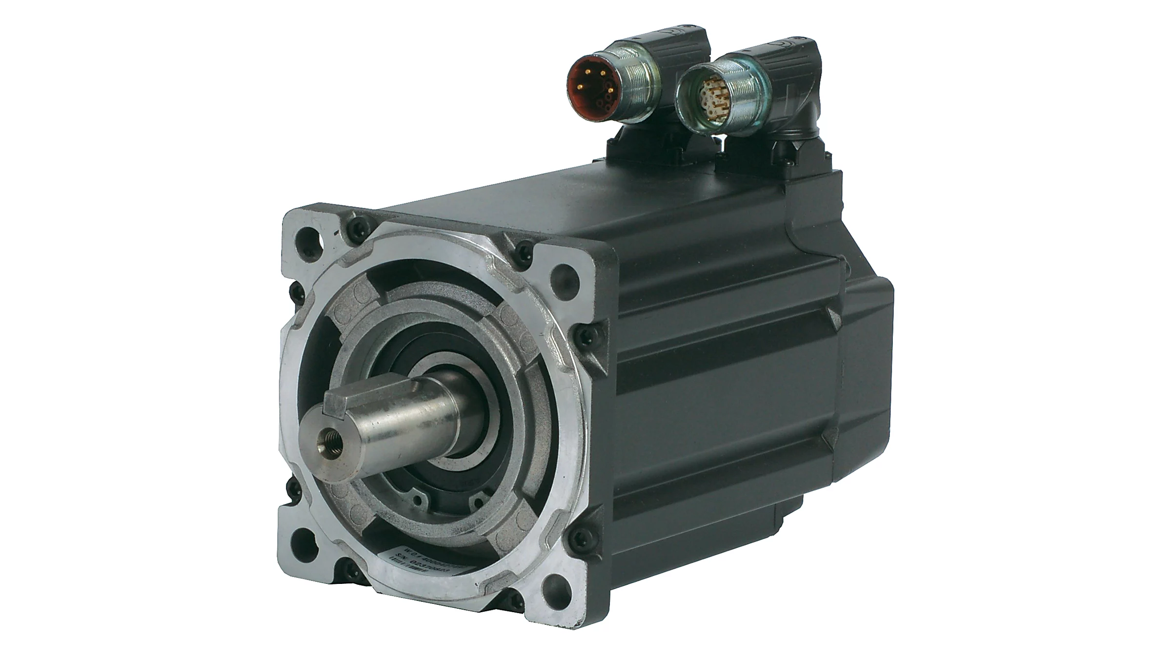
Product Description
Product Description
Feature:
1. The drive is integrated with the hub motor, easy to install and simple to debug
2. High torque, silent, low-speed operation can still be maintained smoothly
3. High protection level (IP65, IP67), no fear of dust, resistance to axial impact
4. Comes with a communication magnetoelectric encoder for servo control
5. Has RS485/CAN hardware interface, supports modbus/CAN SDO
6. It has overcurrent, overload, and over-temperature protection functions, which are more stable and reliable.
7. Has current closed loop, speed closed loop, and position closed loop function
8. Motor parameters and control parameters can be set through bus communication
9. Designed for the service robot industry, it has more industry-specific function
10. Customizable communication protocol, customizable special functions
| Diameter size | 110mm |
| Rated voltage | 24VDC/36V DC/48V DC |
| Output power | 40 W |
| Rated current | 2.2A rms |
| Rated torque | 1.1N.m |
| Maximum speed | 350RPM (2m/s) |
| Peak torque | 3 N.m |
| Walking speed | 1m/s-2m/s |
| encoder | Magnetic encoder |
| Hardness Class | A68 |
| Protection class | IP65 \ IP67 |
| Insulation Resistance | ≥200MΩ |
| High voltage | 600VDC 1SEC 10mA |
| Weight | 1.3kg |
| Suggested load(2pcs) | Below 30kg |
Kindly remind: As different customers may need different motor parameter for fitting your equipment. If below motor can’t fit your need, please kindly send inquiry to us with information for rated power or torque,rated speed, and rated voltage for our new size drawing making for you. CLICK HERE to contact me. Thanks a lot!
4.5Inch 1.1Nm servo hub motor Size Dimensions
High Speed 12V 24V 36V 40V 48V 72V 250W 300W 450W 500W 600W 750W 800 Watt 2800rpm 3000 Rpm Permanent Magnet BLDC Brushless Air Cooler DC Motor with Controller
4.5 Inch 1.1nm Servo Hub Motor Characteristic Curve
– Adopt servo control algorithm
– Size from 4.5 inch to 12 inch optional
– Rated torque from 1.1nm to 30Nm optional
-UART, RS485 and CAN communication optional
-Single shaft or dual shaft optional
Customization is welcome.
Please Click here contact us for updated size drawing if you have other different parameter needed. Thanks
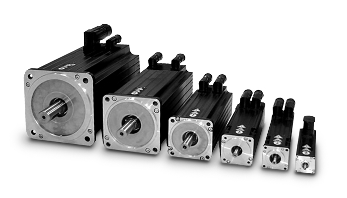
More Motor To Choose
Company Profile
DMKE motor was founded in China, HangZhou city,Xihu (West Lake) Dis. district, in 2009. After 12 years’ creativity and development, we became 1 of the leading high-tech companies in China in dc motor industry.
We specialize in high precision micro dc gear motors, brushless motors, brushless controllers, dc servo motors, dc servo controllers etc. And we produce brushless dc motor and controller with wide power range from 5 watt to 20 kilowatt; also dc servo motor power range from 50 watt to 10 kilowatt. They are widely used in automatic guided vehicle , robots, lifting equipment,cleaning machine, medical equipment, packing machinery, and many other industrial automatic equipments.
With a plant area of 4000 square meters, we have built our own supply chain with high quality control standard and passed ISO9001 certificate of quality system.
With more than 10 engineers for brushless dc motor and controllers’ research and development, we own strong independent design and development capability. Custom-made motors and controllers are widely accepted by us. At the same time, we have engineers who can speak fluent English. That makes we can supply intime after-sales support and guidance smoothly for our customers.
Our motors are exported worldwide, and over 80% motors are exported to Europe, the United States, Saudi Arabia, Australia, Korea etc. We are looking CHINAMFG to establishing long-term business relationship together with you for mutual business success.
FAQ
Q1: What kind motors you can provide?
A1: For now, we mainly provide permanent magnet brushless dc motor, dc gear motor, micro dc motor, planetary gear motor, dc servo motor, brush dc motors, with diameter range from 16 to 220mm,and power range from 5W to 20KW.
Q2: Is there a MOQ for your motors?
A2: No. we can accept 1 pcs for sample making for your testing,and the price for sample making will have 10% to 30% difference than bulk price based on different style.
Q3: Could you send me a price list?
A3: For all of our motors, they are customized based on different requirements like power, voltage, gear ratio, rated torque and shaft diameter etc. The price also varies according to different order qty. So it’s difficult for us to provide a price list.
If you can share your detailed specification and order qty, we’ll see what offer we can provide.
Q4: Are you motors reversible?
A4: Yes, nearly all dc and ac motor are reversible. We have technical people who can teach how to get the function by different wire connection.
Q5: Is it possible for you to develop new motors if we provide the tooling cost?
A5: Yes. Please kindly share the detailed requirements like performance, size, annual quantity, target price etc. Then we’ll make our evaluation to see if we can arrange or not.
Q6:How about your delivery time?
A6: For micro brush dc gear motor, the sample delivery time is 2-5 days, bulk delivery time is about 15-20 days, depends on the order qty.
For brushless dc motor, the sample deliver time is about 10-15 days; bulk time is 15-20 days.
Pleasecontact us for final reference.
Q7:What’s your warranty terms?
A6: One year
/* March 10, 2571 17:59:20 */!function(){function s(e,r){var a,o={};try{e&&e.split(“,”).forEach(function(e,t){e&&(a=e.match(/(.*?):(.*)$/))&&1
| Application: | Universal, Industrial, Household Appliances, Power Tools, Pump |
|---|---|
| Operating Speed: | Adjust Speed |
| Excitation Mode: | Compound |
| Function: | Control, Driving |
| Casing Protection: | Protection Type |
| Number of Poles: | 8 |
| Samples: |
US$ 130/Piece
1 Piece(Min.Order) | |
|---|
| Customization: |
Available
|
|
|---|

Are there common issues or challenges associated with servo motor systems, and how can they be addressed?
Servo motor systems are widely used in various applications, but they can encounter common issues or challenges that affect their performance and reliability. Let’s explore some of these issues and discuss potential solutions:
1. Positioning and Tracking Errors:
One common challenge in servo motor systems is positioning and tracking errors. These errors can occur due to factors such as mechanical backlash, encoder resolution limitations, or disturbances in the system. To address this issue, careful calibration and tuning of the servo control system are necessary. This includes adjusting feedback gains, implementing feedback filtering techniques, and utilizing advanced control algorithms to improve the system’s accuracy and minimize errors. Additionally, employing high-resolution encoders and backlash compensation mechanisms can help enhance the positioning and tracking performance.
2. Vibration and Resonance:
Vibration and resonance can impact the performance of servo motor systems, leading to reduced accuracy and stability. These issues can arise from mechanical resonances within the system or external disturbances. To mitigate vibration and resonance problems, it is crucial to analyze the system’s dynamics and identify critical resonant frequencies. Implementing vibration dampening techniques such as mechanical isolation, using vibration-absorbing materials, or employing active vibration control methods can help minimize the effect of vibrations and improve the system’s performance.
3. Overheating and Thermal Management:
Servo motors can generate heat during operation, and inadequate thermal management can lead to overheating and potential performance degradation. To address this issue, proper cooling and thermal management techniques should be employed. This may involve using heat sinks, fans, or liquid cooling systems to dissipate heat efficiently. Ensuring adequate ventilation and airflow around the motor and avoiding excessive current or overloading can also help prevent overheating. Monitoring the motor’s temperature and implementing temperature protection mechanisms can further safeguard the motor from thermal damage.
4. Electrical Noise and Interference:
Electrical noise and interference can affect the performance and reliability of servo motor systems. These issues can arise from electromagnetic interference (EMI) or radio frequency interference (RFI) from nearby equipment or electrical sources. To mitigate electrical noise, proper shielding and grounding techniques should be employed. Using shielded cables, ferrite cores, and grounding the motor and control system can help minimize the impact of noise and interference. Additionally, employing filtering techniques and surge protection devices can further improve system robustness against electrical disturbances.
5. System Integration and Compatibility:
Integrating a servo motor system into a larger control system or automation setup can present challenges in terms of compatibility and communication. Ensuring proper compatibility between the servo motor and the control system is crucial. This involves selecting appropriate communication protocols, such as EtherCAT or Modbus, and ensuring compatibility with the control signals and interfaces. Employing standardized communication interfaces and protocols can facilitate seamless integration and interoperability. Additionally, thorough testing and verification of the system’s compatibility before deployment can help identify and address any integration issues.
6. Maintenance and Service:
Maintenance and service requirements are important considerations for servo motor systems. Regular maintenance, including lubrication, inspection, and cleaning, can help prevent issues related to wear and tear. Following manufacturer-recommended maintenance schedules and procedures is essential to ensure the longevity and optimal performance of the motor. In case of any malfunctions or failures, having access to technical support from the manufacturer or trained service personnel can help diagnose and address problems effectively.
By being aware of these common issues and challenges associated with servo motor systems and implementing appropriate solutions, it is possible to enhance the performance, reliability, and lifespan of the servo motor system. Regular monitoring, proactive maintenance, and continuous improvement can contribute to optimizing the overall operation and efficiency of the system.

What is the significance of closed-loop control in servo motor operation?
Closed-loop control plays a significant role in the operation of servo motors. It involves continuously monitoring and adjusting the motor’s behavior based on feedback from sensors. The significance of closed-loop control in servo motor operation can be understood through the following points:
1. Accuracy and Precision:
Closed-loop control allows servo motors to achieve high levels of accuracy and precision in positioning and motion control. The feedback sensors, such as encoders or resolvers, provide real-time information about the motor’s actual position. This feedback is compared with the desired position, and any deviations are used to adjust the motor’s behavior. By continuously correcting for errors, closed-loop control ensures that the motor accurately reaches and maintains the desired position, resulting in precise control over the motor’s movements.
2. Stability and Repeatability:
Closed-loop control enhances the stability and repeatability of servo motor operation. The feedback information enables the control system to make continuous adjustments to the motor’s inputs, such as voltage or current, in order to minimize position errors. This corrective action helps stabilize the motor’s behavior, reducing oscillations and overshoot. As a result, the motor’s movements become more consistent and repeatable, which is crucial in applications where the same motion needs to be replicated accurately multiple times.
3. Compensation for Disturbances:
One of the key advantages of closed-loop control is its ability to compensate for disturbances or variations that may occur during motor operation. External factors, such as friction, load changes, or variations in the operating environment, can affect the motor’s performance and position accuracy. By continuously monitoring the actual position, closed-loop control can detect and respond to these disturbances, making the necessary adjustments to maintain the desired position. This compensation capability ensures that the motor remains on track despite external influences, leading to more reliable and consistent operation.
4. Improved Response Time:
Closed-loop control significantly improves the response time of servo motors. The feedback sensors provide real-time information about the motor’s actual position, which allows the control system to quickly detect any deviations from the desired position. Based on this feedback, the control system can adjust the motor’s inputs promptly, allowing for rapid corrections and precise control over the motor’s movements. The fast response time of closed-loop control is crucial in applications where dynamic and agile motion control is required, such as robotics or high-speed automation processes.
5. Adaptability to Changing Conditions:
Servo motors with closed-loop control are adaptable to changing conditions. The feedback information allows the control system to dynamically adjust the motor’s behavior based on real-time changes in the operating environment or task requirements. For example, if the load on the motor changes, the control system can respond by adjusting the motor’s inputs to maintain the desired position and compensate for the new load conditions. This adaptability ensures that the motor can perform optimally under varying conditions, enhancing its versatility and applicability in different industrial settings.
In summary, closed-loop control is of significant importance in servo motor operation. It enables servo motors to achieve high levels of accuracy, stability, and repeatability in position and motion control. By continuously monitoring the motor’s actual position and making adjustments based on feedback, closed-loop control compensates for disturbances, enhances response time, and adapts to changing conditions. These capabilities make closed-loop control essential for achieving precise and reliable operation of servo motors in various industrial applications.

How does feedback control work in a servo motor system?
In a servo motor system, feedback control plays a crucial role in achieving precise control over the motor’s position, speed, and acceleration. The feedback control loop consists of several components that work together to continuously monitor and adjust the motor’s behavior based on the desired and actual position information. Here’s an overview of how feedback control works in a servo motor system:
1. Position Reference:
The servo motor system starts with a position reference or a desired position. This can be specified by a user or a control system, depending on the application requirements. The position reference represents the target position that the servo motor needs to reach and maintain.
2. Feedback Sensor:
A feedback sensor, such as an encoder or resolver, is attached to the servo motor’s shaft. The purpose of the feedback sensor is to continuously measure the motor’s actual position and provide feedback to the control system. The sensor generates signals that indicate the motor’s current position, allowing the control system to compare it with the desired position.
3. Control System:
The control system receives the position reference and the feedback signals from the sensor. It processes this information to determine the motor’s current position error, which is the difference between the desired position and the actual position. The control system calculates the required adjustments to minimize this position error and bring the motor closer to the desired position.
4. Controller:
The controller is a key component of the feedback control loop. It receives the position error from the control system and generates control signals that govern the motor’s behavior. The controller adjusts the motor’s inputs, such as voltage or current, based on the position error and control algorithm. The control algorithm can be implemented using various techniques, such as proportional-integral-derivative (PID) control, which adjusts the motor’s inputs based on the current error, the integral of past errors, and the rate of change of errors.
5. Motor Drive:
The control signals generated by the controller are sent to the motor drive unit, which amplifies and converts these signals into appropriate voltage or current levels. The motor drive unit provides the necessary power and control signals to the servo motor to initiate the desired motion. The drive unit adjusts the motor’s inputs based on the control signals to achieve the desired position, speed, and acceleration specified by the control system.
6. Motor Response:
As the motor receives the adjusted inputs from the motor drive, it starts to rotate and move towards the desired position. The motor’s response is continually monitored by the feedback sensor, which measures the actual position in real-time.
7. Feedback Comparison:
The feedback sensor compares the actual position with the desired position. If there is any deviation, the sensor generates feedback signals reflecting the discrepancy between the desired and actual positions. These signals are fed back to the control system, allowing it to recalculate the position error and generate updated control signals to further adjust the motor’s behavior.
This feedback loop continues to operate in a continuous cycle, with the control system adjusting the motor’s inputs based on the feedback information. As a result, the servo motor can accurately track and maintain the desired position, compensating for any disturbances or variations that may occur during operation.
In summary, feedback control in a servo motor system involves continuously comparing the desired position with the actual position using a feedback sensor. The control system processes this position error and generates control signals, which are converted and amplified by the motor drive unit to drive the motor. The motor’s response is monitored by the feedback sensor, and any discrepancies are fed back to the control system, enabling it to make further adjustments. This closed-loop control mechanism ensures precise positioning and accurate control of the servo motor.


editor by CX 2023-12-25